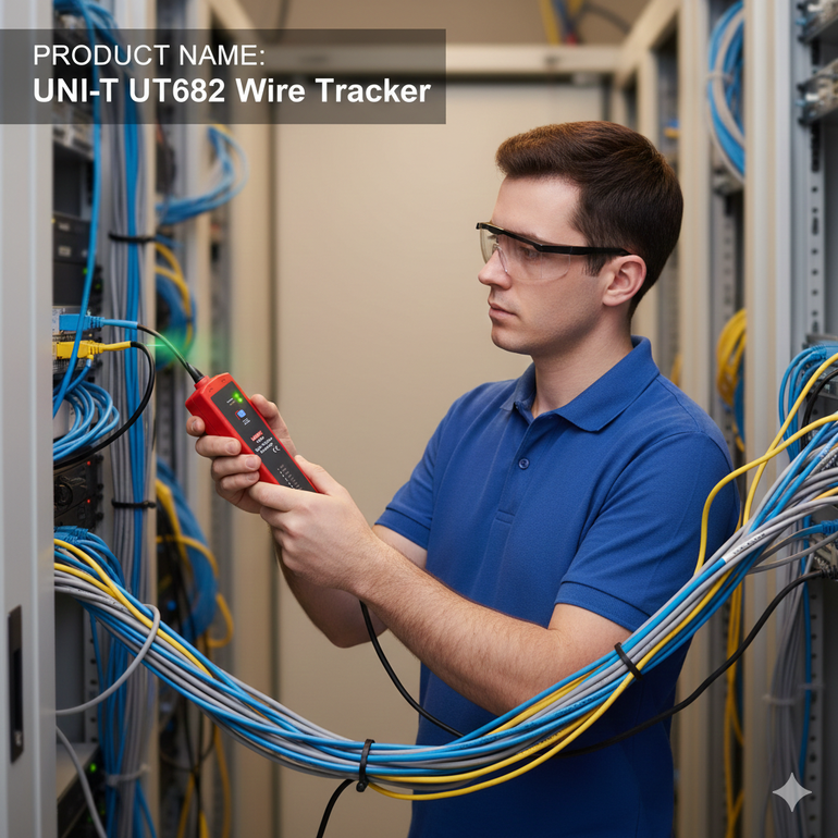
Wire and cable tracer/tracker | UT682
The UNI-T UT682 is a device for accurately tracing and testing network, telephone, and electrical cables. It features a tracing range of up to 3000m, short-circuit and polarity testing, and adjustable sensitivity. It is easy to use with SCAN tracing more information
SAR 595.00
+
Earn loyalty points with this purchase
Rewardsproduct sku
Weight
share product
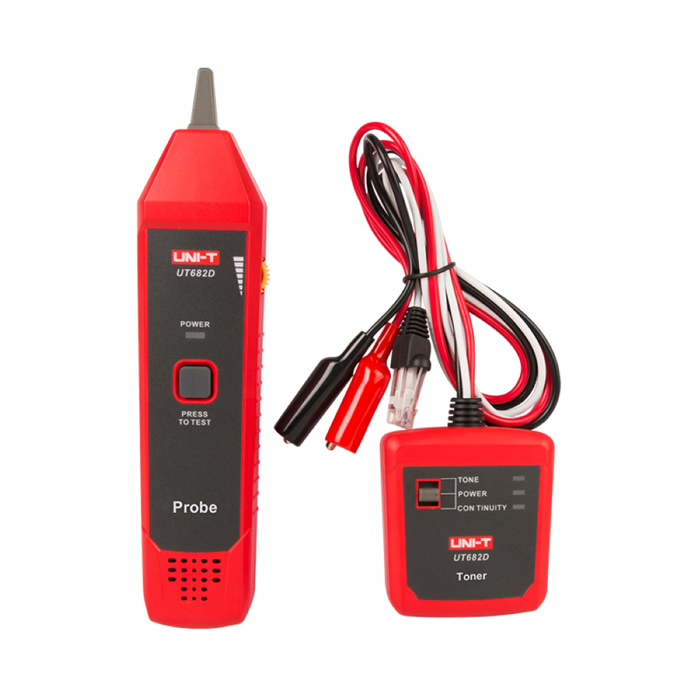
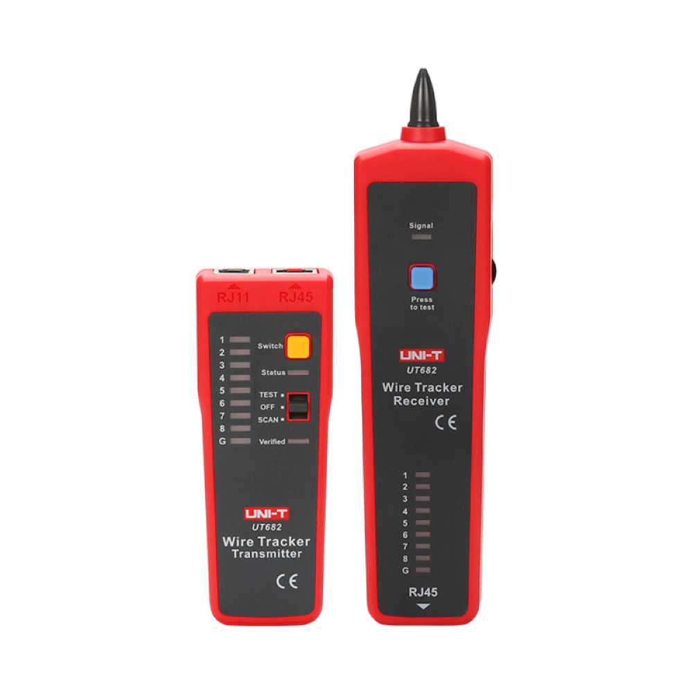
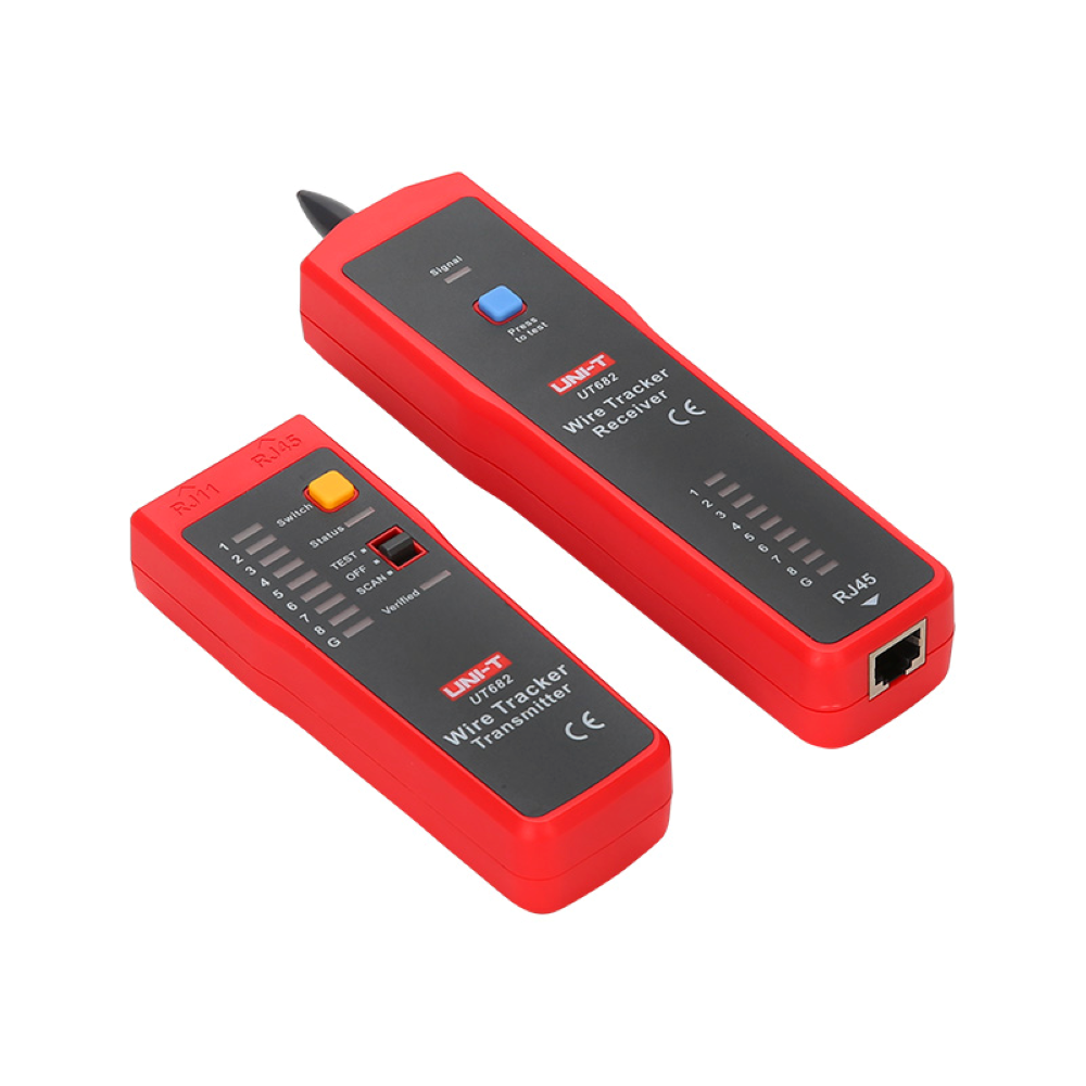
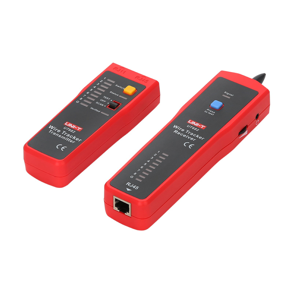
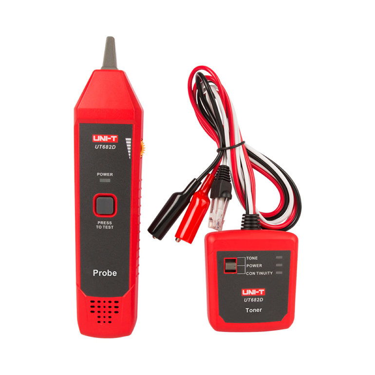
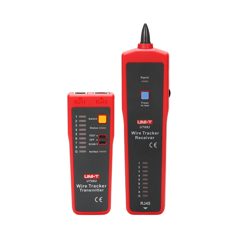
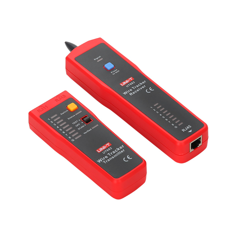
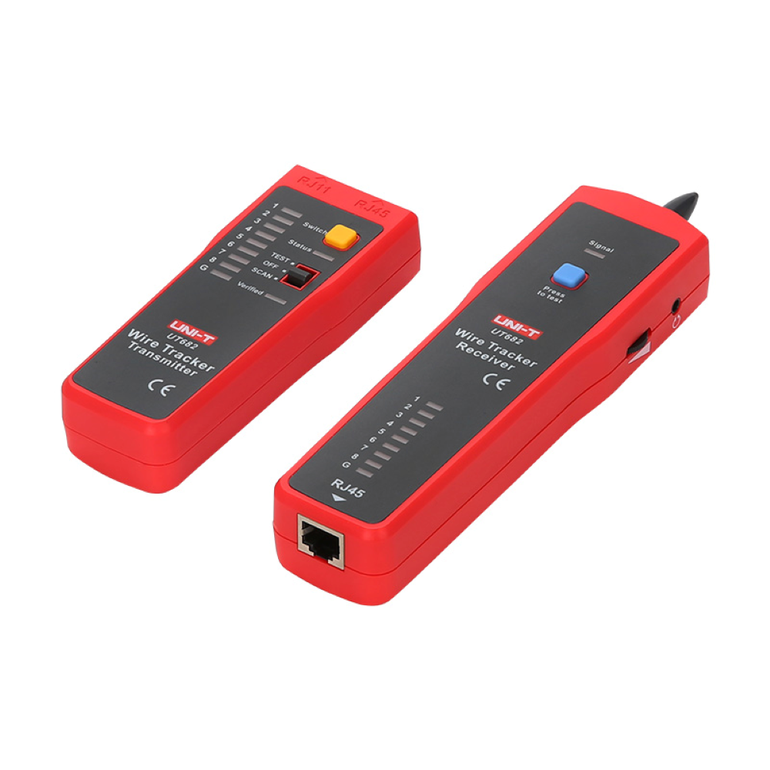
The UNI-T UT682 is a professional, all-in-one tool designed for tracking and testing cables and wires (Network, Telephone, and Electrical) without damaging the insulation. The device consists of two units: a Transmitter and a Receiver.
1. Technical Specifications
- Supported Cable Types: LAN cables, telephone lines, coaxial cables, and electrical wires.
- Wire Tracking Distance:
- Telephone lines: ≥ 3000 meters.
- Network cables (Shielded and Unshielded): ≥ 320 meters.
- Testing Functions: Open circuit and short circuit detection.
- Telephone Polarity Indicator: Available for telephone lines (Range: ±5V to ±52V).
- Transmitter Output Voltage: ≥ 12V (Peak-to-Peak).
- Power Supply: 9V battery (one for the transmitter and one for the receiver).
- Voltage Protection: DC voltage protection up to 52V.
- Dimensions: Transmitter (125 x 48 x 28 mm), Receiver (195 x 48 x 30 mm).
2. Key Features
- Multi-purpose Tracking: Ability to track telephone, internet, and live electrical cables.
- Wire Sequence Verification: Verifies the wiring order of network cables (RJ45) and detects connection errors.
- Sensitivity Control: Features a rotary dial on the receiver to adjust volume and sensitivity.
- Headphone Jack: Allows operation in noisy environments.
- LED Indicators: Displays signal strength and battery status.
- Speed Modes: Switch between fast and slow test modes.
3. Operating Instructions (How to Use)
A. Wire Tracking
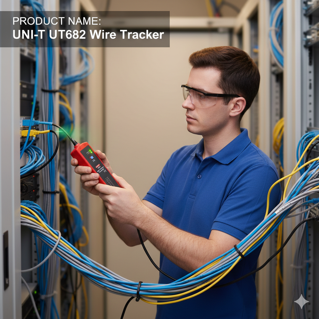
Connect the target wire to the (RJ11 or RJ45) port on the transmitter. Set the transmitter switch to SCAN. Use the receiver, press the power button, and move the probe near the wire bundle. A buzzer will sound when the correct wire is detected.
B. Network Cable Alignment
Insert both ends of the RJ45 cable into the transmitter and receiver. Set the transmitter to TEST. The LED lights (1-8) will flash in sequence to verify the connection.
C. Polarity Test
Use the included alligator clips with the transmitter. Connect the clips to the telephone wires. A green LED indicates correct polarity, while a red LED indicates reversed polarity.
4. Package Contents
- Transmitter and Receiver units.
- Two 9V batteries.
- RJ11 and RJ45 cables.
- RJ11 cable with Alligator clips.
- Carrying bag and user manual.
Safety Warning: Do not use the device on high-voltage circuits (above 52V DC) to avoid device damage or electric shock.